


The Rudolph Record A Mechanical Engineering Portfolio Vol. I · No. 1
The Rudolph
Record
Mechanical Engineering Portfolio✦Madison, Wisconsin

Lead Story · The Engineer

Building the machines that move people safely

Levi Rudolph, a mechanical engineering student at UW–Madison, works where project management meets the design of safety-critical systems.

By Levi Rudolph · Mechanical Engineering, Class of 2028


Fig. 1 · Front Page
Class-4 suspended ride vehicle, modelled to ASTM F2291 — one of seven cases in this edition.

A mechanical engineering student at UW–Madison working in project management, technical project engineering, and the mechanical design of safety-critical systems. From launched model coasters to Class-4 restraint hardware, the through-line stays the same — ask the right question before trusting the system that already exists.

Notice
Now accepting Summer 2026 internships.
About
The person behind the by-line

In his own words

I started an engineering club because there wasn't a clear way into themed entertainment. Now it's 340+ members deep, with a seat at ASTM F24, IAAPA, and TMU Thrill Design Comp.

I founded a startup to save project managers hundreds of hours a year — building the mathematically efficient scheduling tool that didn't exist.

“Good engineering lives in the art of asking the right question - not in trusting the systems that already exist.”
Levi Rudolph
Selected Works
Eight cases · 2024–2026

Things I designed, built and broke

Independent
Case No. 01 · 2026

5 DOF Robotic Arm Attraction Model

Fully Custom Arm Down to the Actuator
By L. Rudolph · Filed 2026 · In Progress
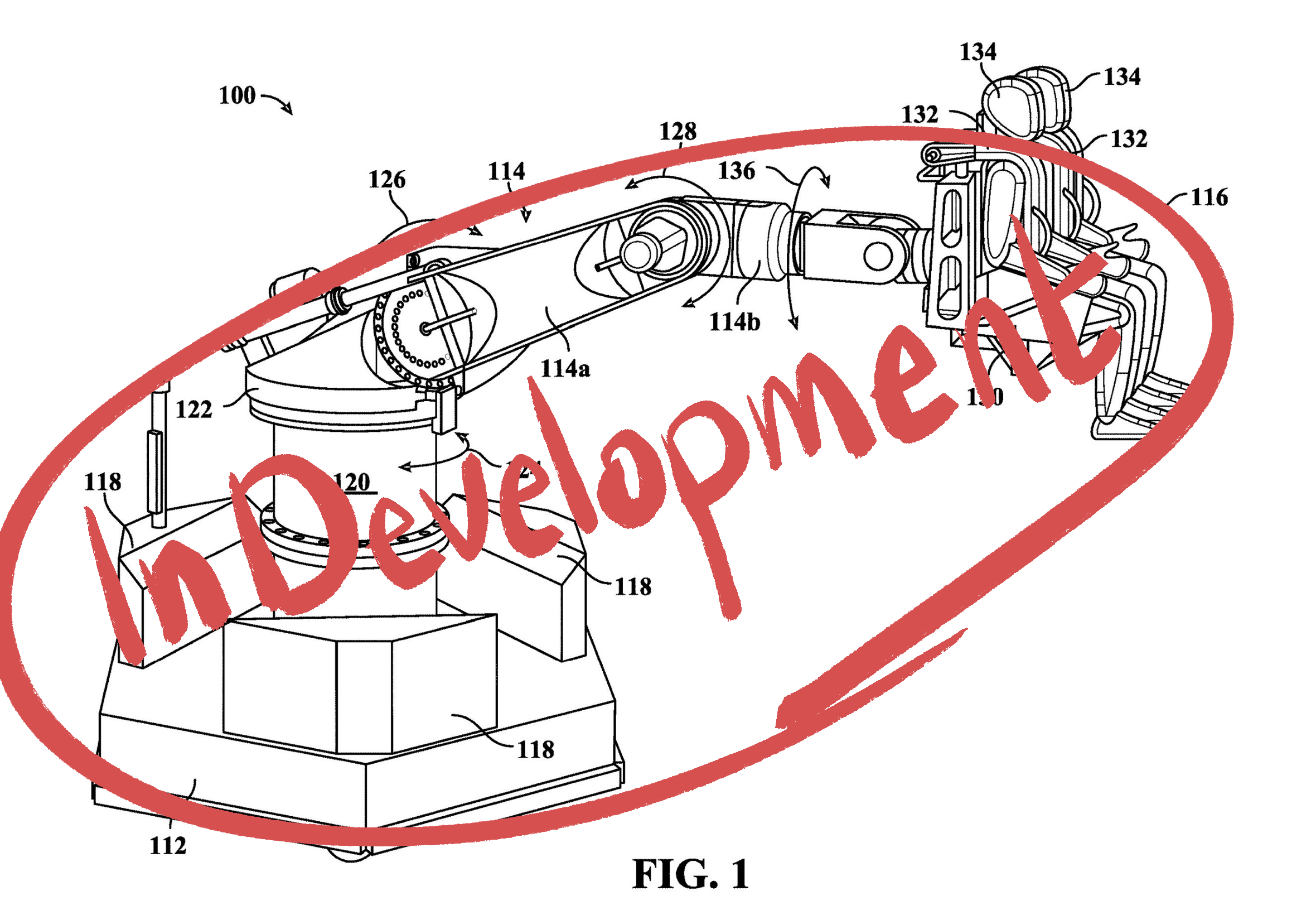
5-DOF robotic arm attraction model
5-DOF robotic arm attraction model.

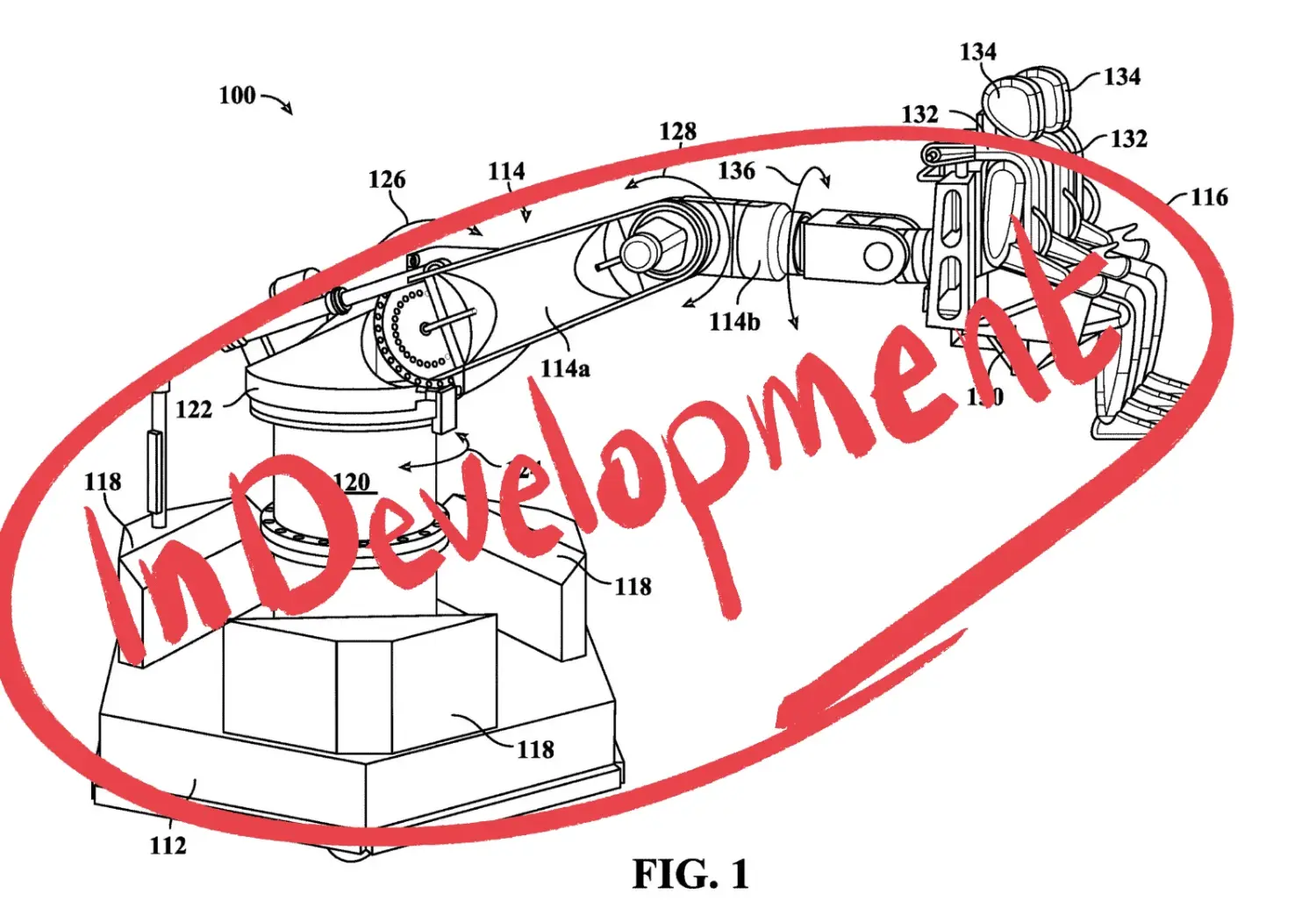
This in development project is a tabletop scale robotic arm with a fully custom engineered design, from the actuators all the way up to the fully ASTM F24 2291 Class-4 Compliant restraint for the bucky badger rider. 

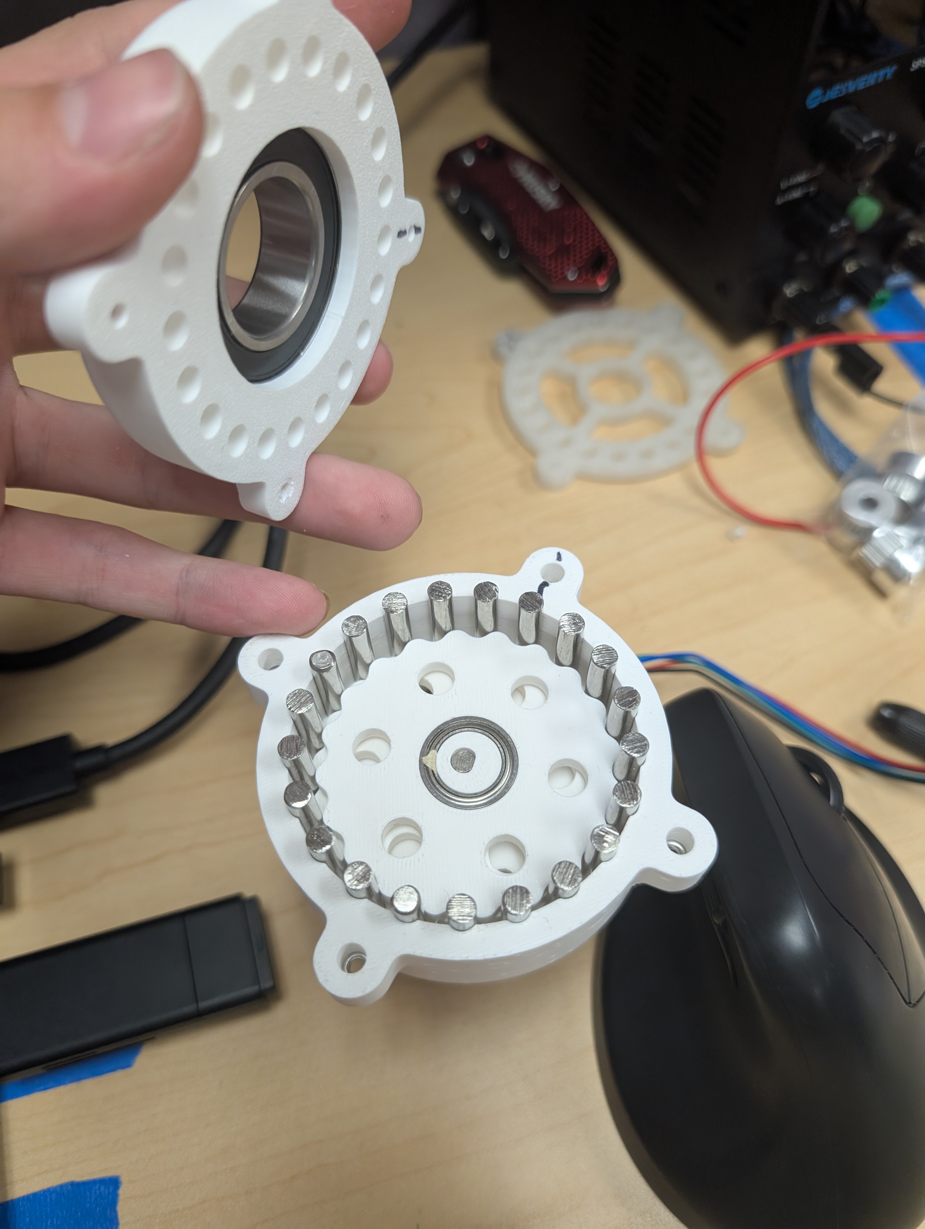
This features a 20:1 Cycloidal Drive, and tight packaging of all the components. The steppers are run from a TMC 2209 Motor Controller with UART communication to an ESP32. 
 The restraint is a ratcheting solenoid activated restraint, with mechanical and electrical compliance with the standard. The ride program features load unload characteristics, preventing the ride cycle to start if the restraints are not locked.

Click for details →
More on the desk
Independent · FounderNo. 02

Attend.

Mass meeting scheduler on custom graph algorithms
By L. Rudolph · Filed 2026 · In Progress
Attend. product screenshot

A meeting scheduler that models availability as a graph and searches it, instead of intersecting calendars and hoping something survives.

Click for details →
BiTE · Chief EngineerNo. 03

Bucky's Blast Off

Launching model roller coaster
By L. Rudolph · Filed 2024

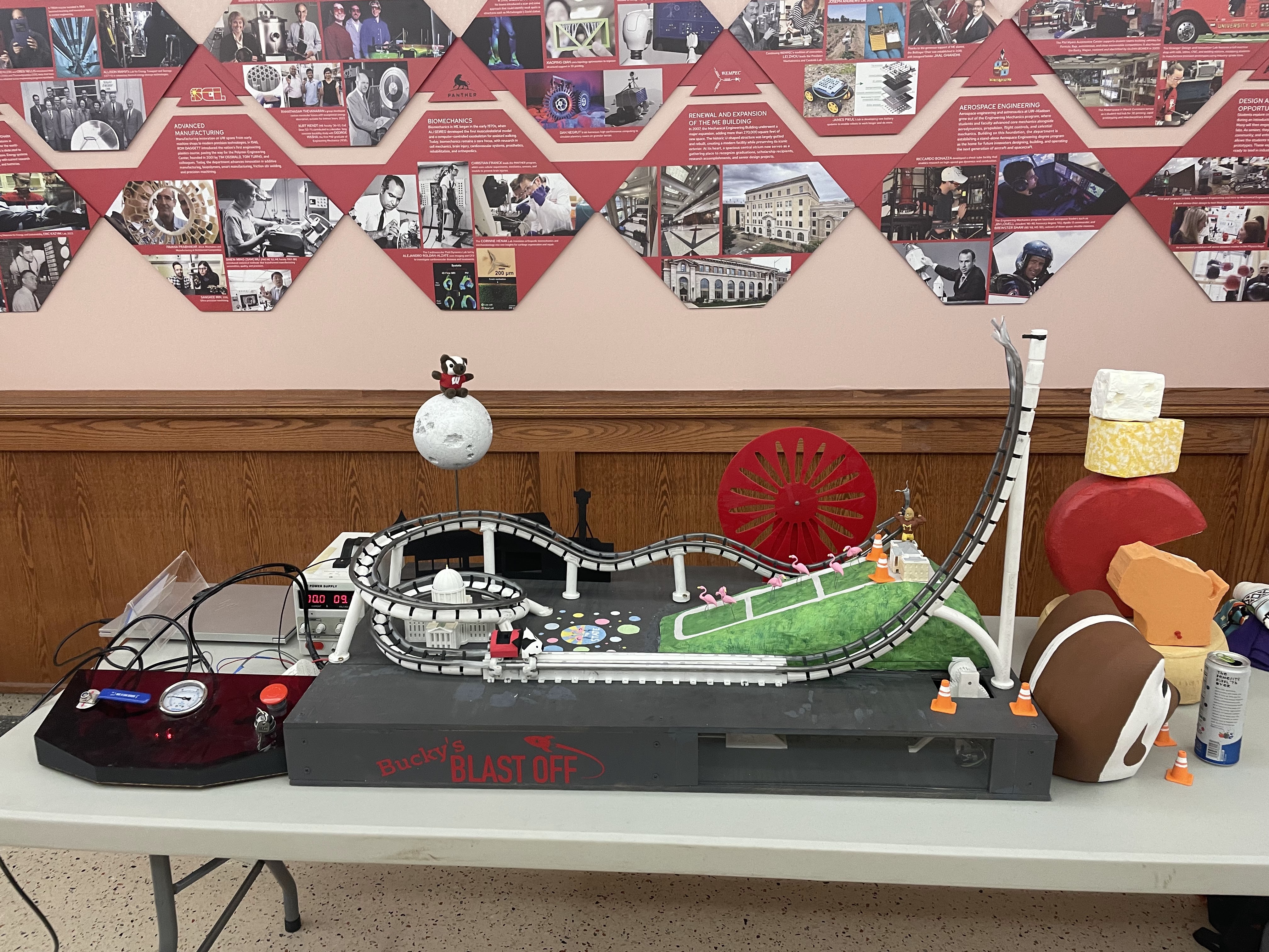
Chief engineer on a 31-person build of a pneumatically launched model coaster — sizing the launch for the exit velocity the layout demanded, checking the acceleration profile through the first element, and setting the fabrication plan so assembly never idled waiting on a part.

Click for details →
BiTE · Chief EngineerNo. 04

ASTM F2291 Class-4 Suspended Ride Vehicle

Suspended coaster vehicle model
By L. Rudolph · Filed 2025

A Class-4 suspended ride vehicle modelled to ASTM F2291 — from restraint geometry to the clearance envelope it sweeps against track and structure.

Click for details →
BiTE · Chief EngineerNo. 05

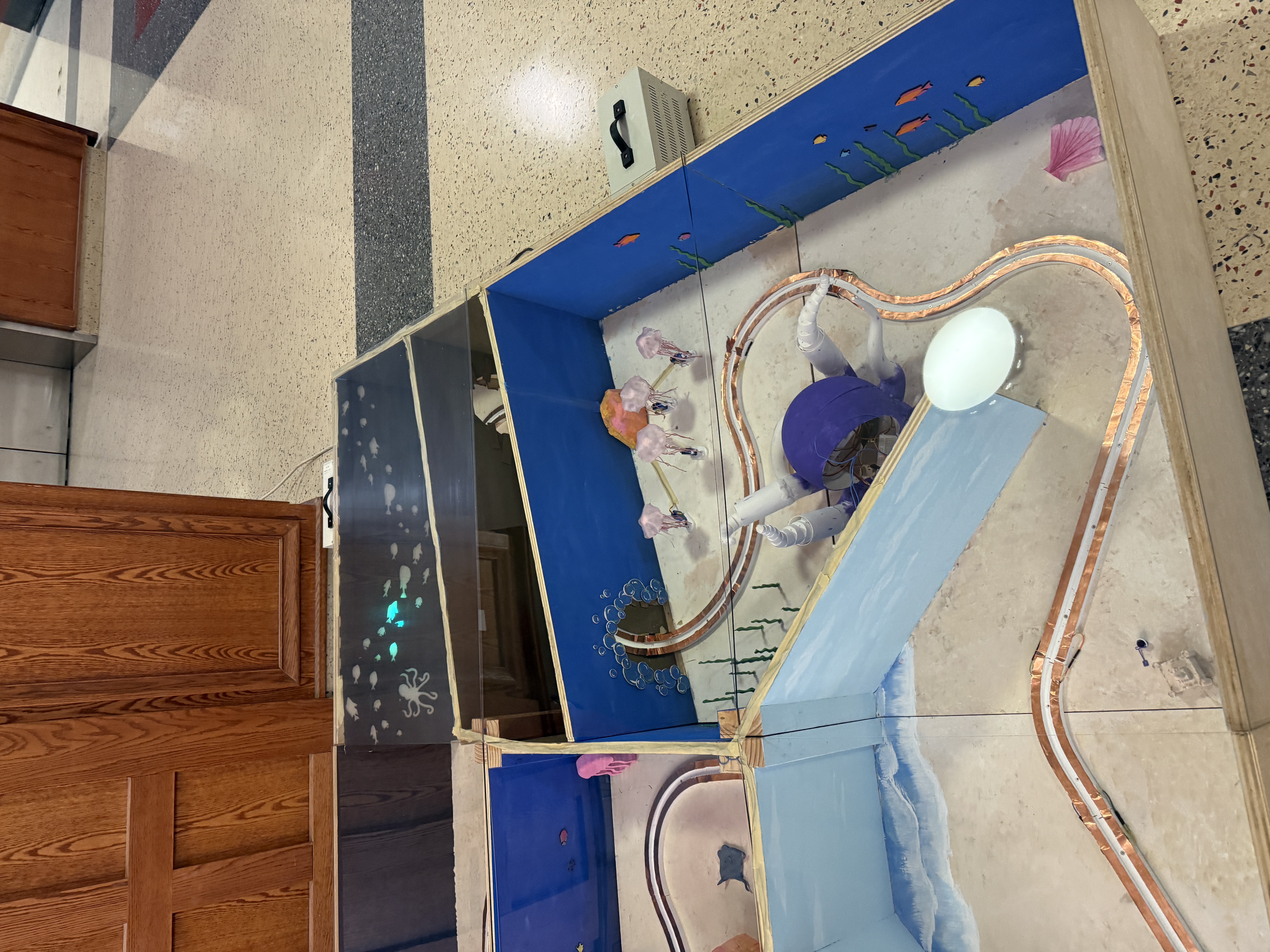
36 sq ft Dark Ride

Physical Model that is live VR-viewable
By L. Rudolph · Filed 2025

A thirty-six-square-foot dark ride, built as a physical model and live viewable through VR.

Click for details →
Technical ReportNo. 06

Additive vs. Subtractive Manufacturing for Aircraft Engine Components

A weighted trade study of two routes for jet-engine parts
By L. Rudolph · Filed 2026
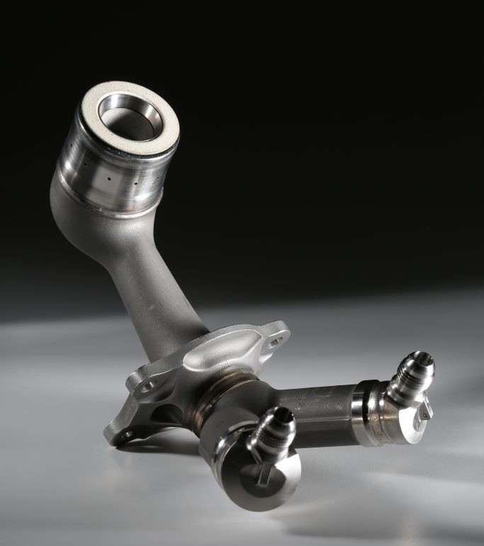
Additively manufactured aircraft engine fuel nozzle

Weighted scoring across five production criteria that ended in a near tie — a more useful answer than a clean winner would have been.

Click for details →
ASTM · Task GroupNo. 07

ASTM F24.80 Harmonization — Historical Change Record

Ride-safety standards historical documentation
By L. Rudolph · Filed 2025 · In Progress
ASTM International

Tracing why each clause was written — the hazard it was meant to address, and the wording the committee rejected on the way there.

Click for details →
Coursework · Team LeadNo. 08

Folding Projector Robot

A concept-to-CAD design study
By L. Rudolph · Filed 2023
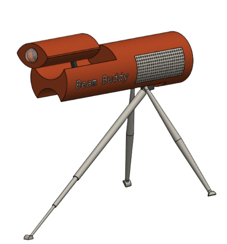
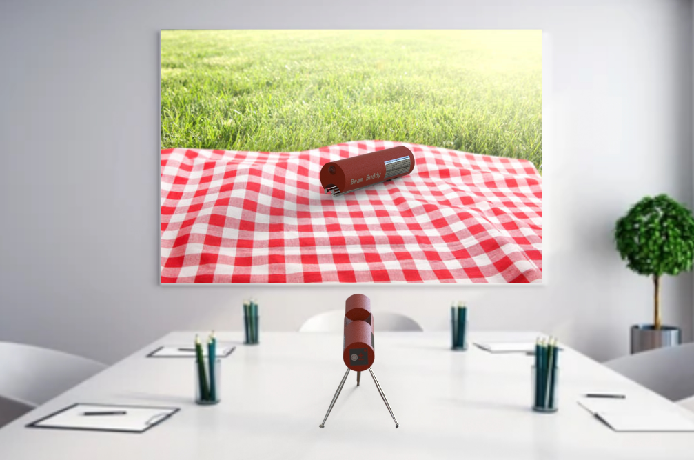
Folding projector robot — Beam Buddy CAD render

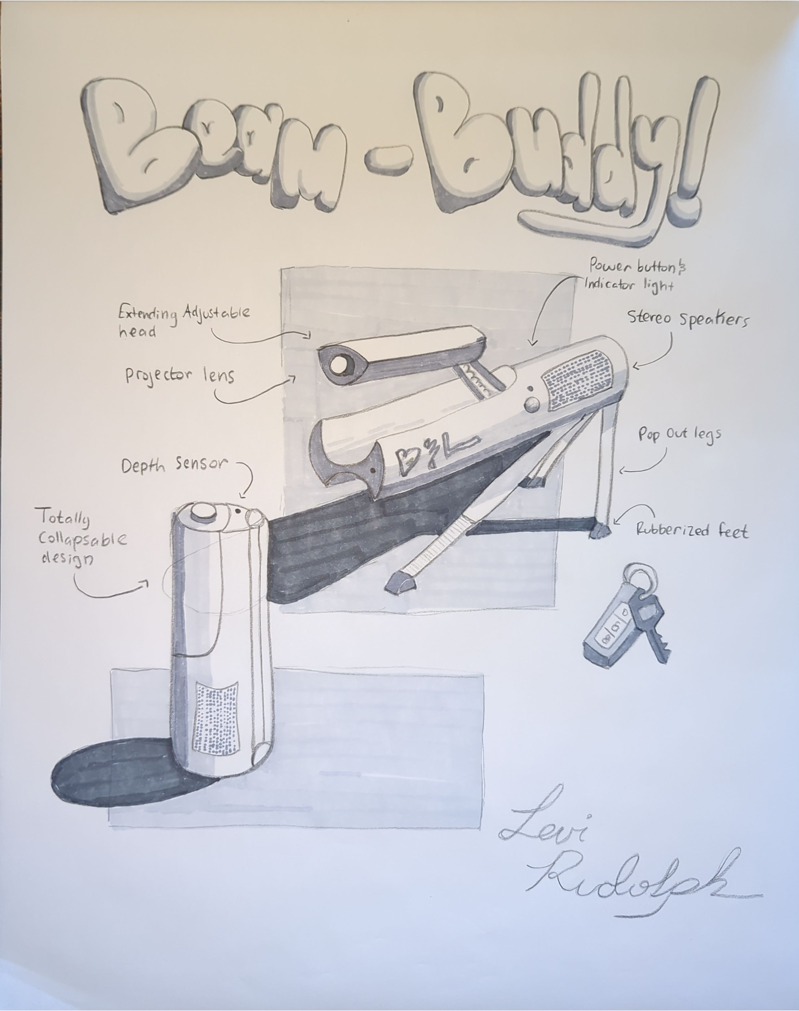
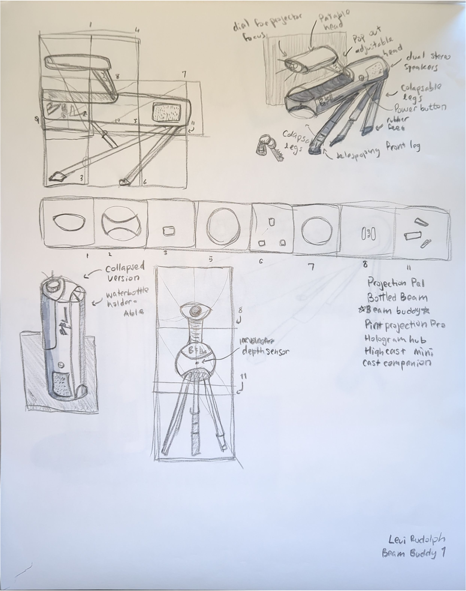
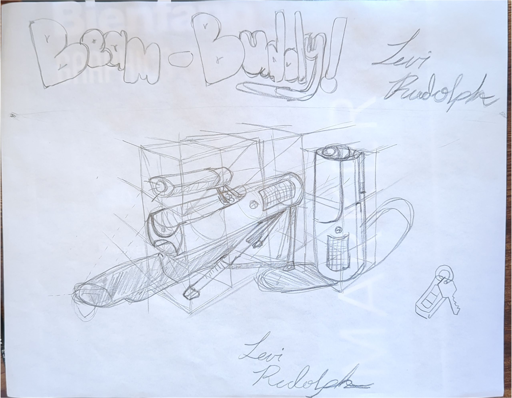
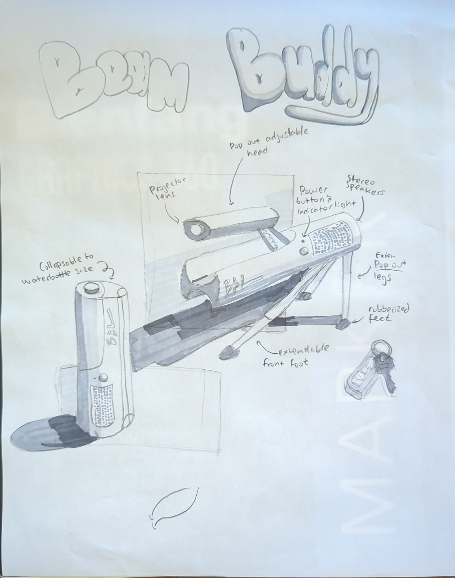
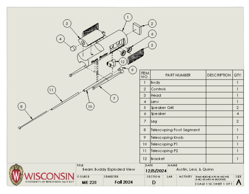
A WALL-E-style projector robot that collapses to the size of a water bottle, then unfolds legs and a head to stand and frame a projected image.

Click for details →
Role
Operations Officer
Team
31 members
Org
BiTE
Tools & Technologies
SolidWorks Kinematic Analysis CNC Milling 3D Printing Laser Cutting Wood Fabrication Scheduling · MS Project Scope & Budget
03  —  Project

Bucky's Blast Off

Launching model roller coaster

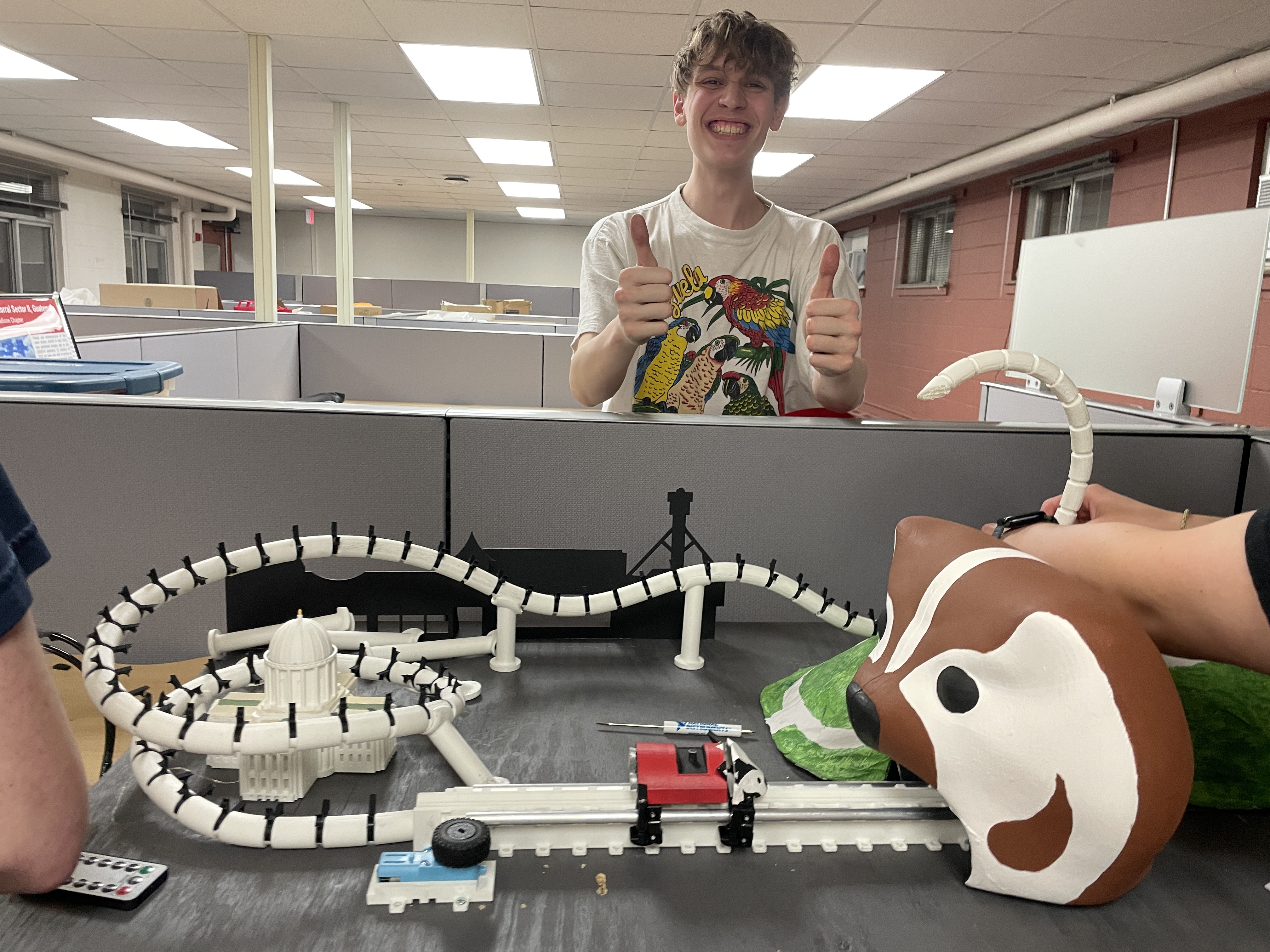
A working model of a pneumatic launch coaster, built on a 31-member team where I led the subsystem leads and personally sat on the launch team doing the launch design and analysis. The mechanism is a compressed-air launch driving a launch dog into the train, the same architecture as MAXX Force at Six Flags Great America. Rather than a full circuit, the layout is a single vertical spike, a choice we made deliberately: a spike shows kids the physics of a launch, kinetic energy trading for height and rolling back, far more clearly than a sprawling layout would.

↓Scroll for write-up & gallery
The launch

The launch was engineered to a hard target. I worked the kinematics to size the launch so the train exits at exactly the velocity needed to reach the top of the 26″ spike and roll back cleanly, no more and no less. That meant calculating launch acceleration, exit velocity, and spike clearance, then reconciling them against the losses in the real system. The biggest of those losses was the surprise: track friction during fabrication came in far higher than predicted and was killing our exit speed. The fix was unglamorous and effective. Graphite powder on the track dropped the friction enough to hit the target, and it stuck.

The train

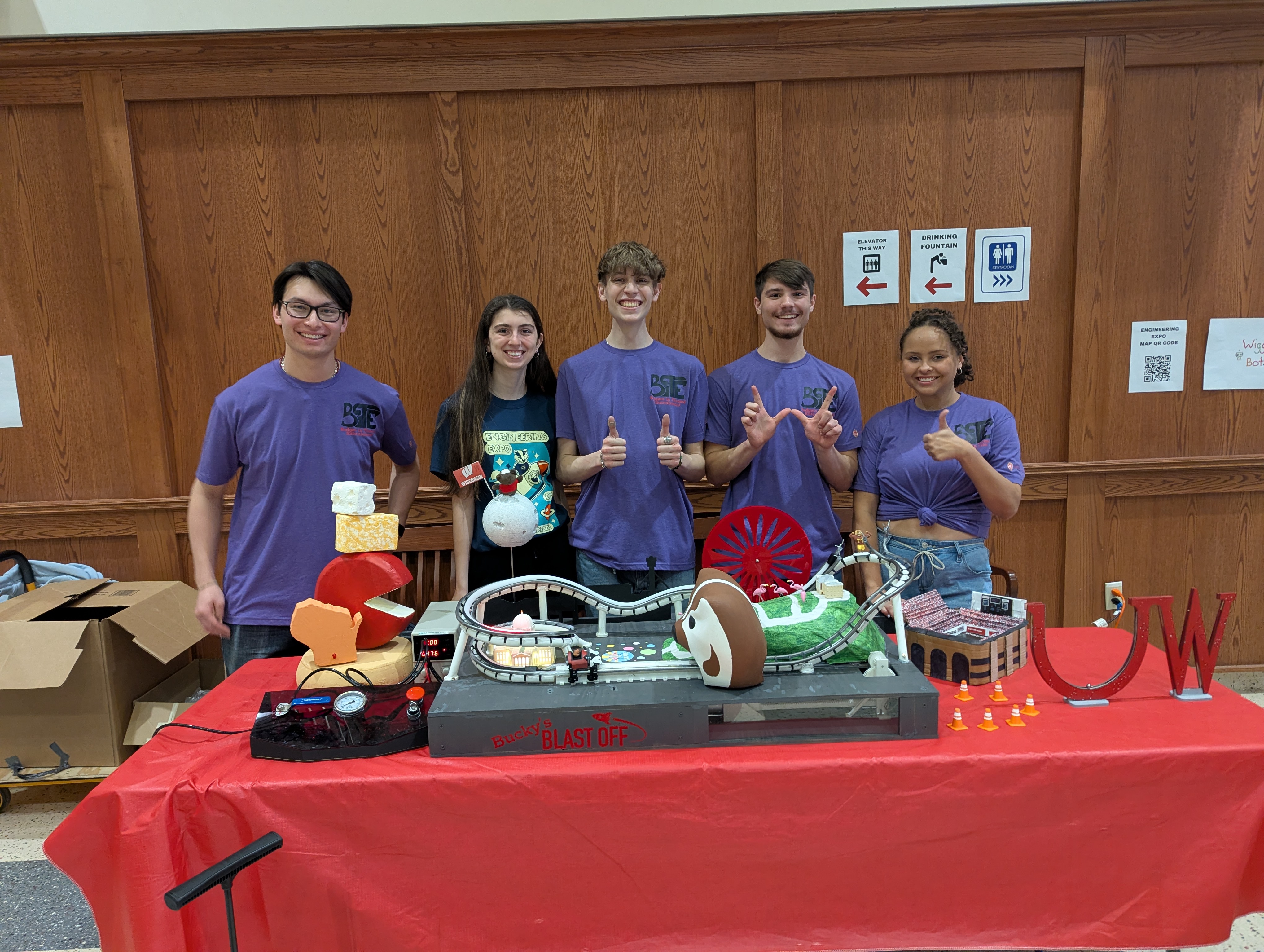
The train itself is a themed Bucky rocket ship, 4″ long and about 2.5″ wide, carrying the club's professor as its rider. It was demonstrated at Engineering Expo as part of the booth that won Best in Show.

The number

The number I point to is reliability: the model has run over 5,000 cycles across two years of demonstration with zero maintenance. For a student-built mechanism with a pneumatic launch and moving train, that is the real proof it was engineered, not just assembled.

Gallery
Bucky's Blast Off model — full layout with vertical spike
Track and themed show elements up close
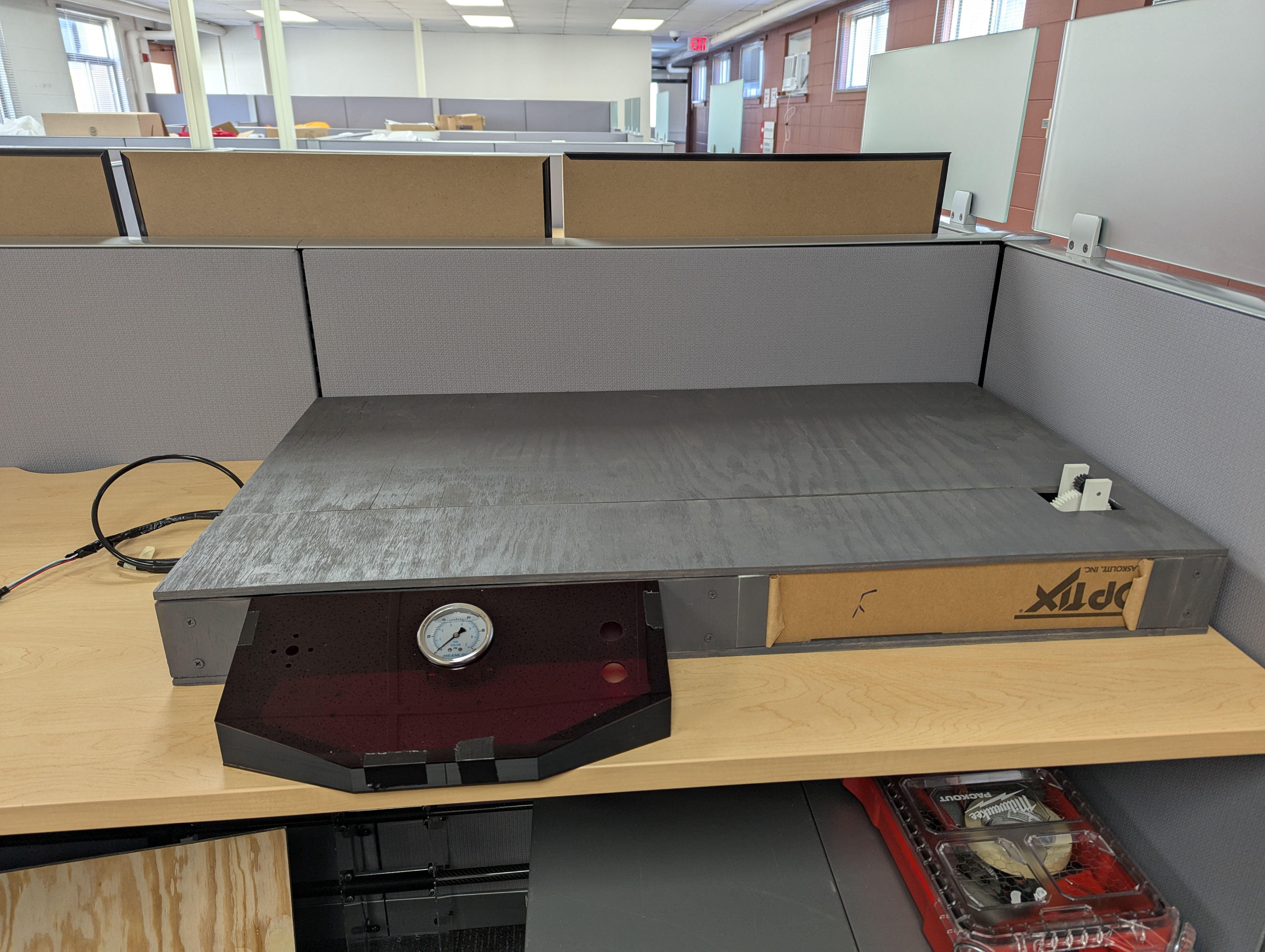
Pneumatic launch base with rack drive
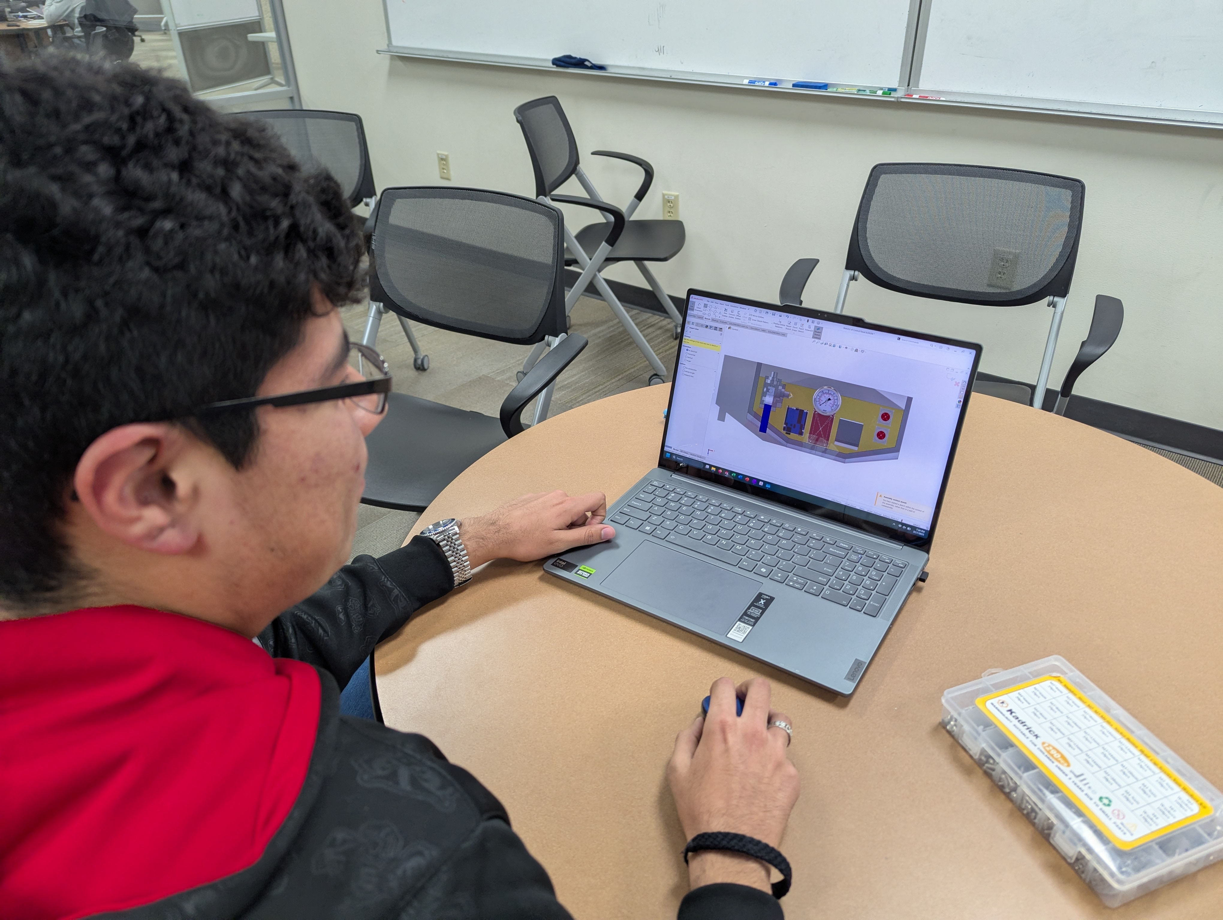
Reviewing the launch assembly in SolidWorks
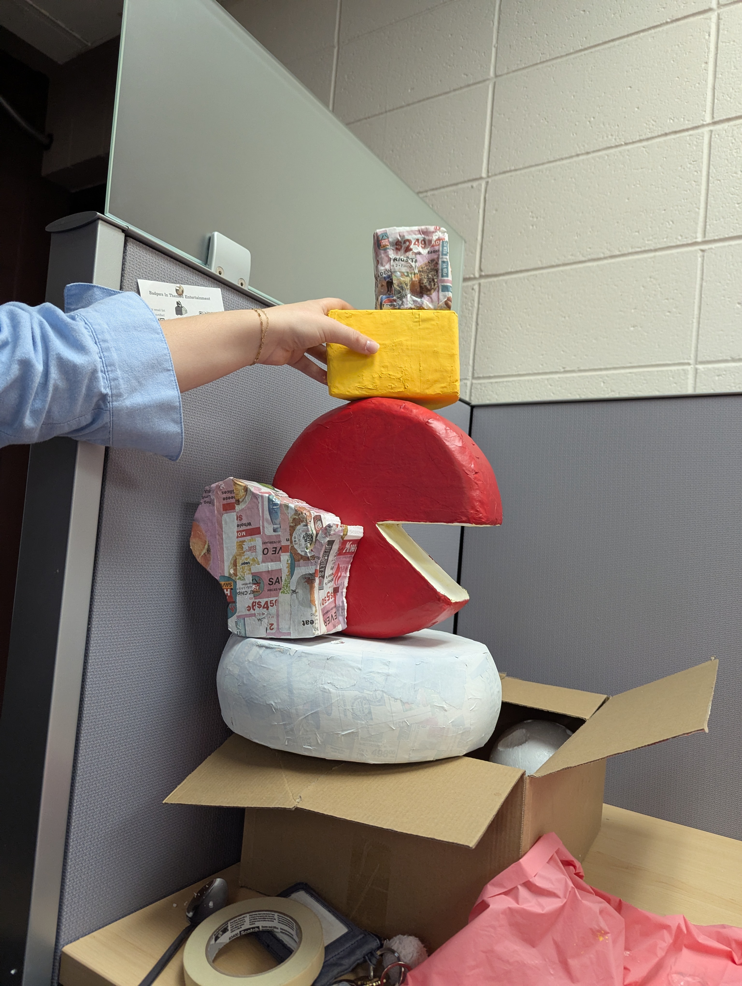
Themed scenic props in fabrication
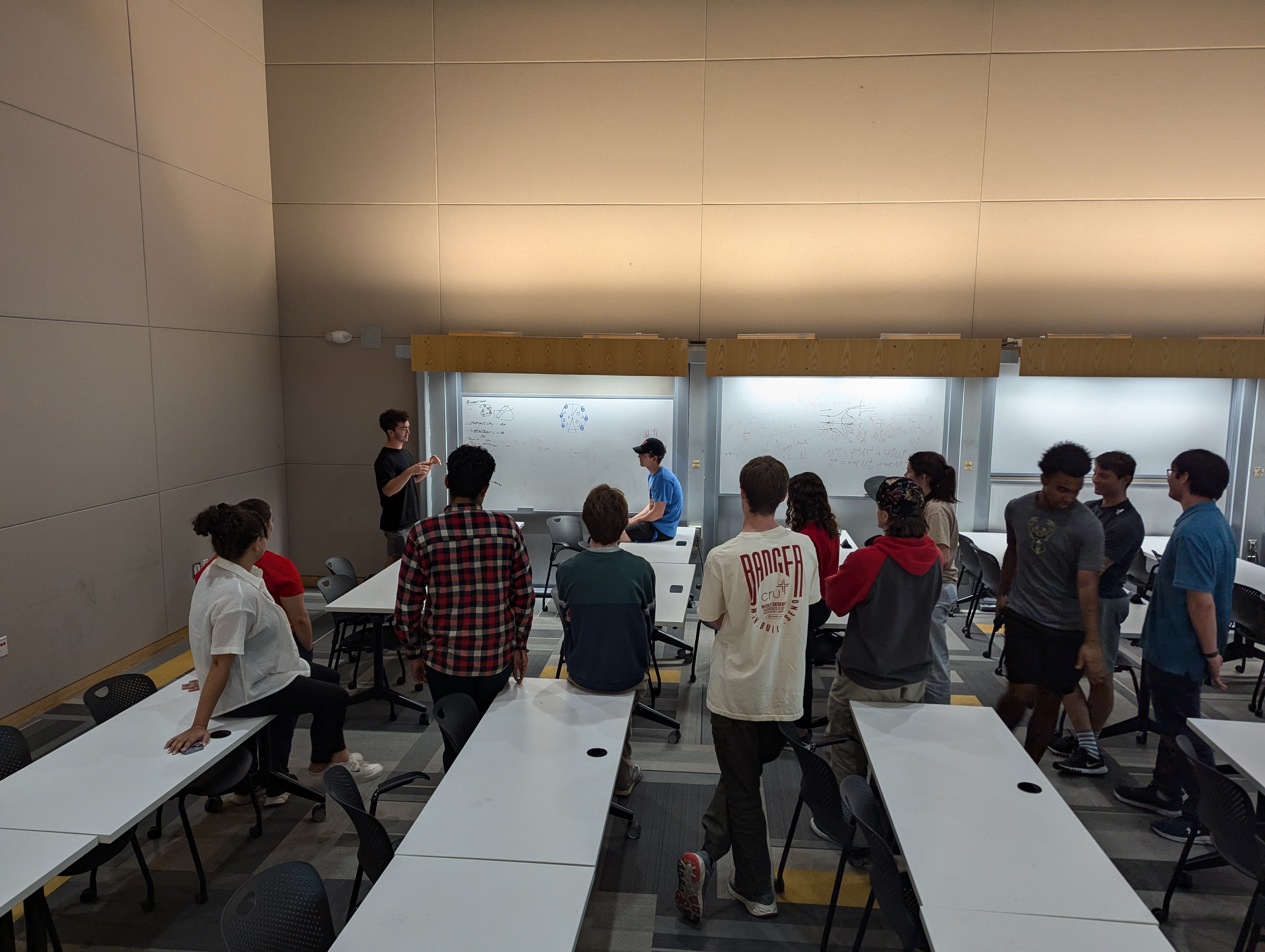
Team design meeting
Bucky's Blast Off at Engineering Expo
The team with the model at Engineering Expo
ASTM International
Role
Task Group Member
Since
2025
Committee
F24.80
Status
In Progress
Tools & Technologies
ASTM F24 Human Factors
08  —  Project

ASTM F24.80 Harmonization — Historical Change Record

Ride-safety standards documentation

Ongoing work I am doing on a two-person team through the Next-Gen ASTM group, contributing to F24.80, the harmonization standard for amusement rides and devices. The goal is to build a historical record and change log that captures everything that changed between versions of the standard, and, more importantly, documents why each change was made. Standards evolve version to version, but the reasoning behind a given revision often lives only in the memory of the people who were in the room. Once that context is lost, future committees end up relitigating decisions that were already settled for good reasons. This record is meant to prevent that, giving future standard development a clear line of sight into the intent behind the language it inherits.

↓Scroll for write-up & gallery
Sourcing the “why”

The part that makes this real work rather than a paperwork exercise is how we are sourcing the “why.” Rather than guessing at intent from the redlines, we are conducting technical interviews with the people who actually made the changes, and pairing what they tell us with the version history so each documented change is tied to the reasoning that drove it.

What it represents

The project is in progress. What it represents is unusual for a student: direct involvement inside a working ASTM subcommittee, alongside the industry professionals who write and maintain the safety standards the amusement industry runs on, doing the kind of technical documentation and institutional-memory work that shapes how those standards develop going forward.

Gallery
Role
Chief Engineer
Team
5 members
Standard
ASTM F2291
Tools & Technologies
SolidWorks Kinematic Analysis ASTM F2291 Class-4 Restraint Systems 3D Printing Laser Cutting Wood Fabrication Document Control Scope & Budget
02  —  Project

ASTM F2291 Class-4 Suspended Ride Vehicle

ASTM F2291 Class-4 vehicle model

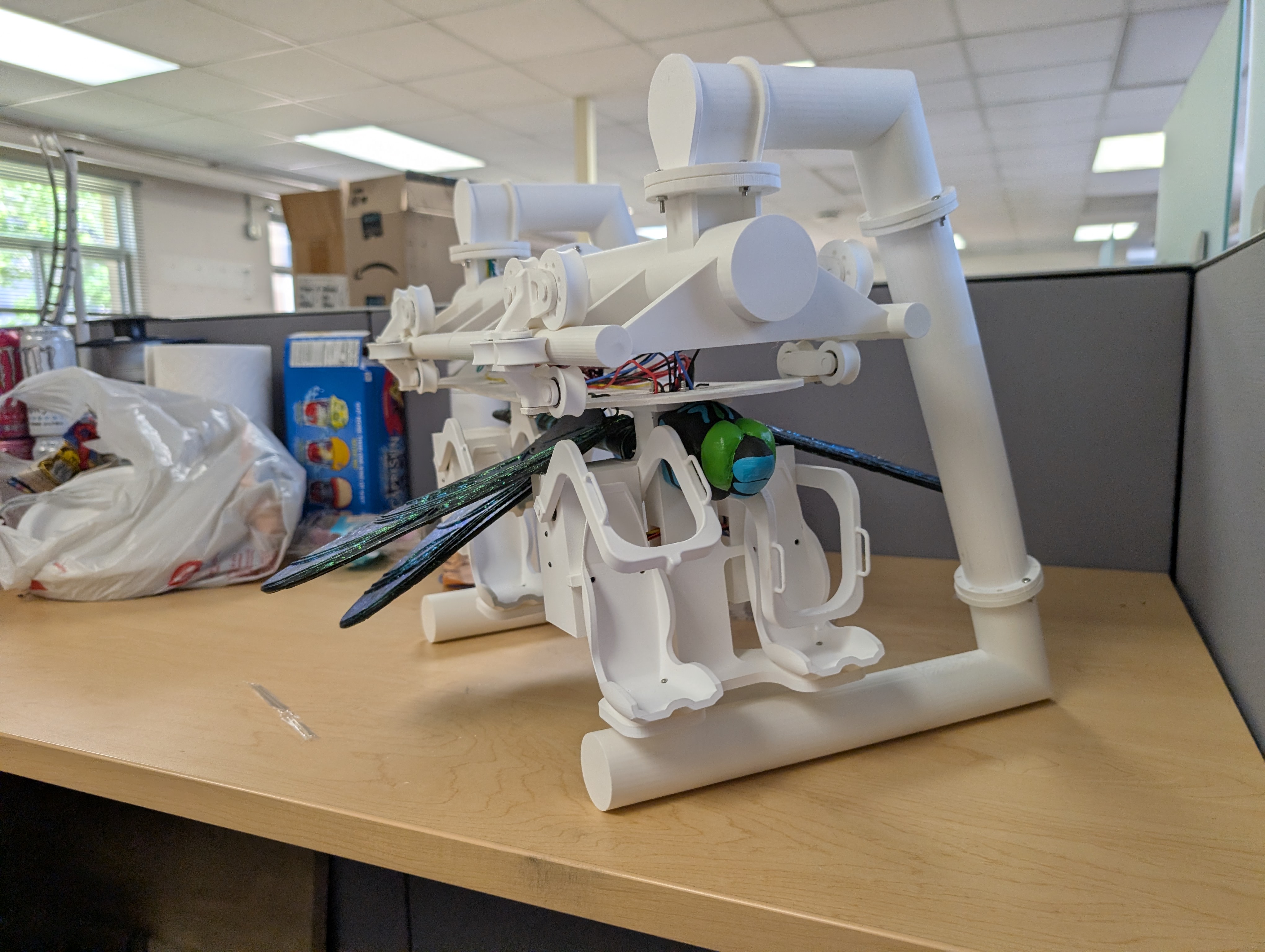
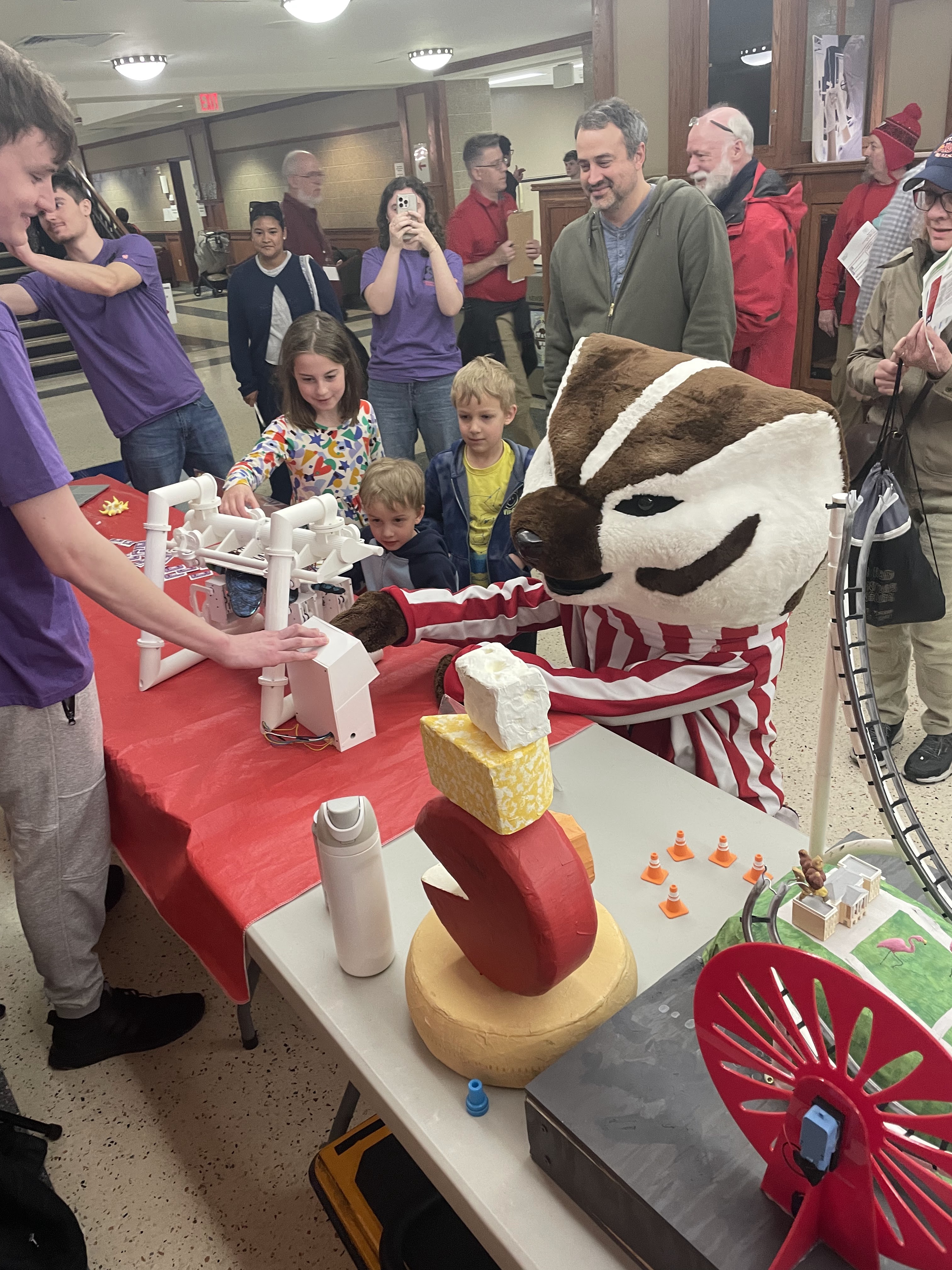
A tabletop working model of an inverted (“suspended”) coaster vehicle, built for Engineering Expo to teach local children how these ride mechanisms work and, more importantly, how they keep riders safe. I led a 5-member team on it. The model is a full ride vehicle plus a track segment and the supports it demonstrates on, presented the way manufacturers show off vehicles at IAAPA rather than as an isolated part on a table. It runs 24″ long and carries a 6″ scale patron.

↓Scroll for write-up & gallery
The restraint

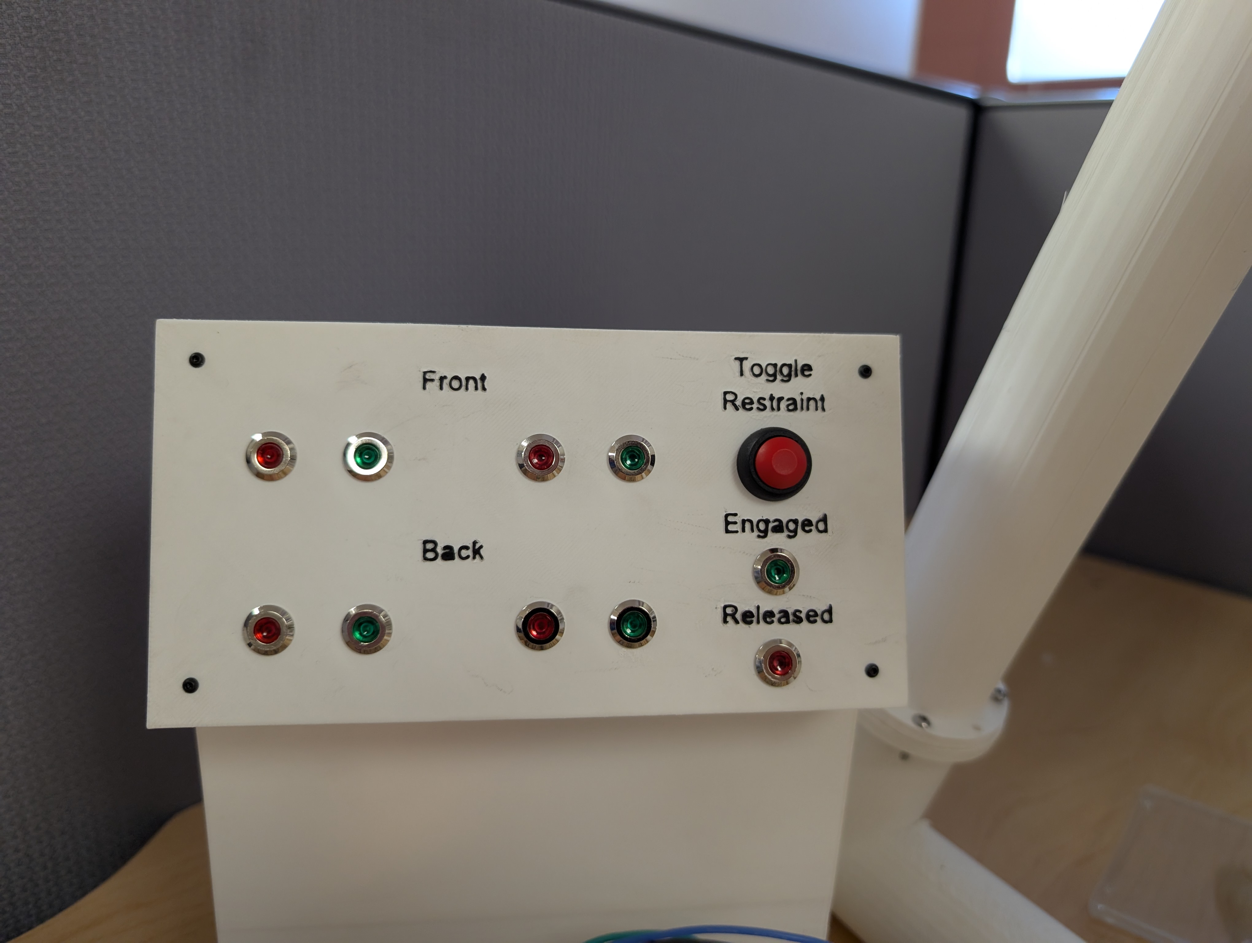
The centerpiece is a dual-redundant, ratcheting over-the-shoulder restraint that is compliant with ASTM F2291 Class-4 both mechanically and electrically, so no single failure in either domain can release the rider. This restraint was the predecessor to the one I later designed for my robotic arm ride model, and it is where the approach was first worked out. The design is backed by real engineering: restraint load cases, structural analysis of the suspension carrying the vehicle under the track, and material and fabrication choices sized to the loads rather than guessed. The vehicle, track, and supports were produced with 3D printing, laser cutting, and CNC machining.

Leading the team

The part I am proudest of as team lead was not any single component. It was getting four other people to actually open the ASTM standard, read it, understand what Class-4 requires, and implement it correctly in hardware. Standards work is where most student projects wave their hands, and turning a dense specification into a fabricated, demonstrable mechanism that a team of five understood end to end is the real result.

The record

The finished model was fabricated and demonstrated at Engineering Expo as part of the booth that won Best in Show.

Gallery
Full suspended ride vehicle and track segment
Restraint engaged/released status panel
The model demonstrated at Engineering Expo
Role
Operations Officer
Team
40 members
Footprint
36 sq ft
Tools & Technologies
SolidWorks 3D Printing Laser Cutting Wood Fabrication Scheduling · MS Project Document Control
04  —  Project

36 sq ft Dark Ride

VR-viewable model attraction

A fully realized dark ride built into a 36 sq ft footprint, with a 40 ft ride path, six show scenes, seven servo-driven animatronics, a themed show set, and a POV camera fixed to the vehicle so the whole thing can be experienced from the guest's seat as if it were full scale. I led the project as Operations Officer on a 40-member team, which meant I ran the subsystem team leads: owning the technical design across subsystems, keeping the track, vehicle, show, and controls teams integrated and unblocked, and steering the engineering and analysis that tied it all together.

↓Scroll for write-up & gallery
The ride

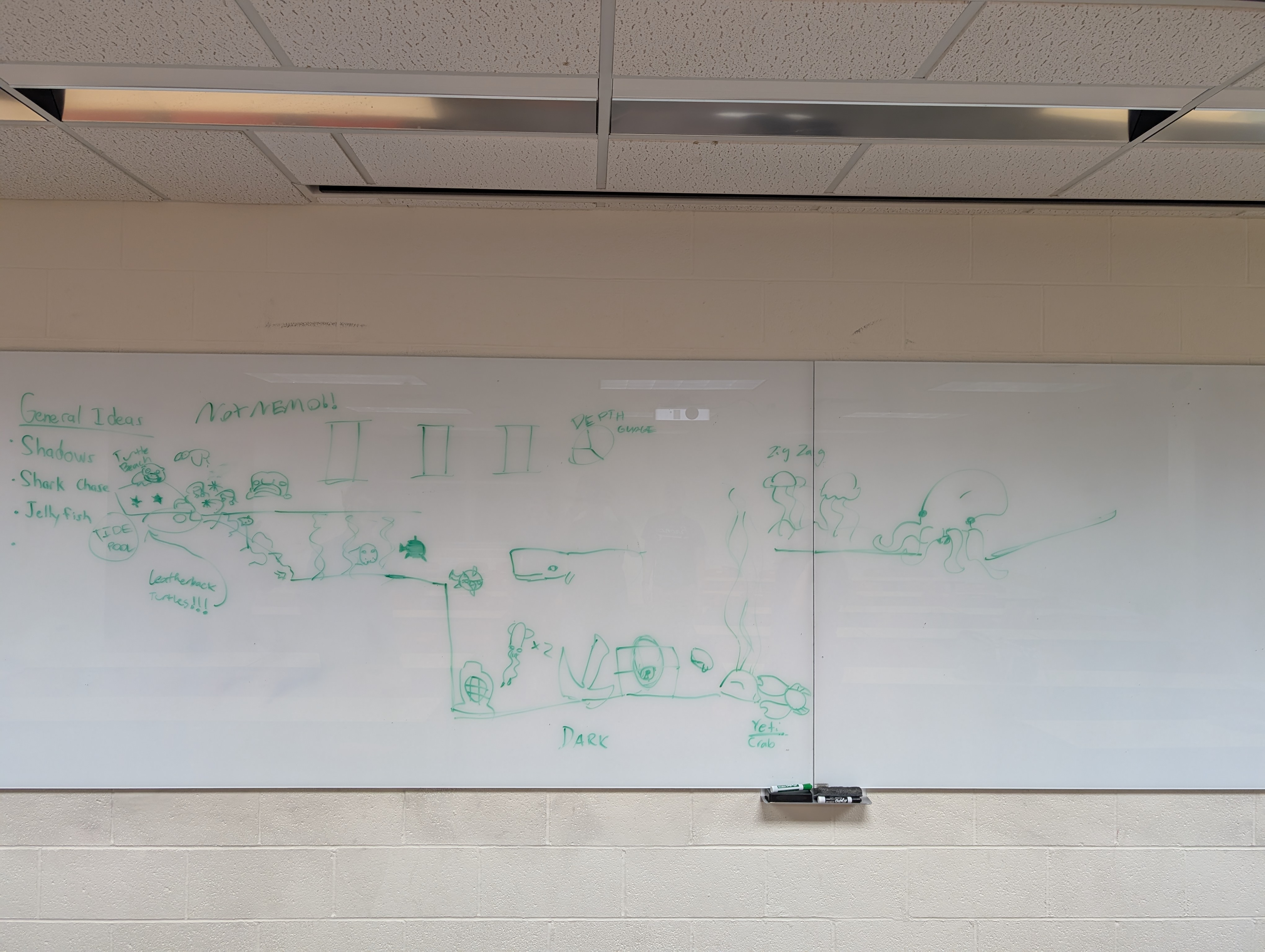
The ride is a tracked, continuously moving system, and it tells a story. The vehicle is a submarine descending deeper and deeper into the ocean: it gets startled by a shark, is guided onward by bioluminescent fish, discovers a wrecked ship, and finishes with a conducting octopus. Each of the seven animatronics runs on its own Arduino Nano, all coordinated by a master ESP32 that sequences the animatronics against the vehicle's motion so scenes trigger on cue as the sub arrives.

Hands-on engineering

Beyond the leadership role, I did hands-on engineering: I designed the ride enclosure and the cable routing for the whole model, and I led the track and ride vehicle team closely enough to be in the mechanical design, not just managing it.

The record

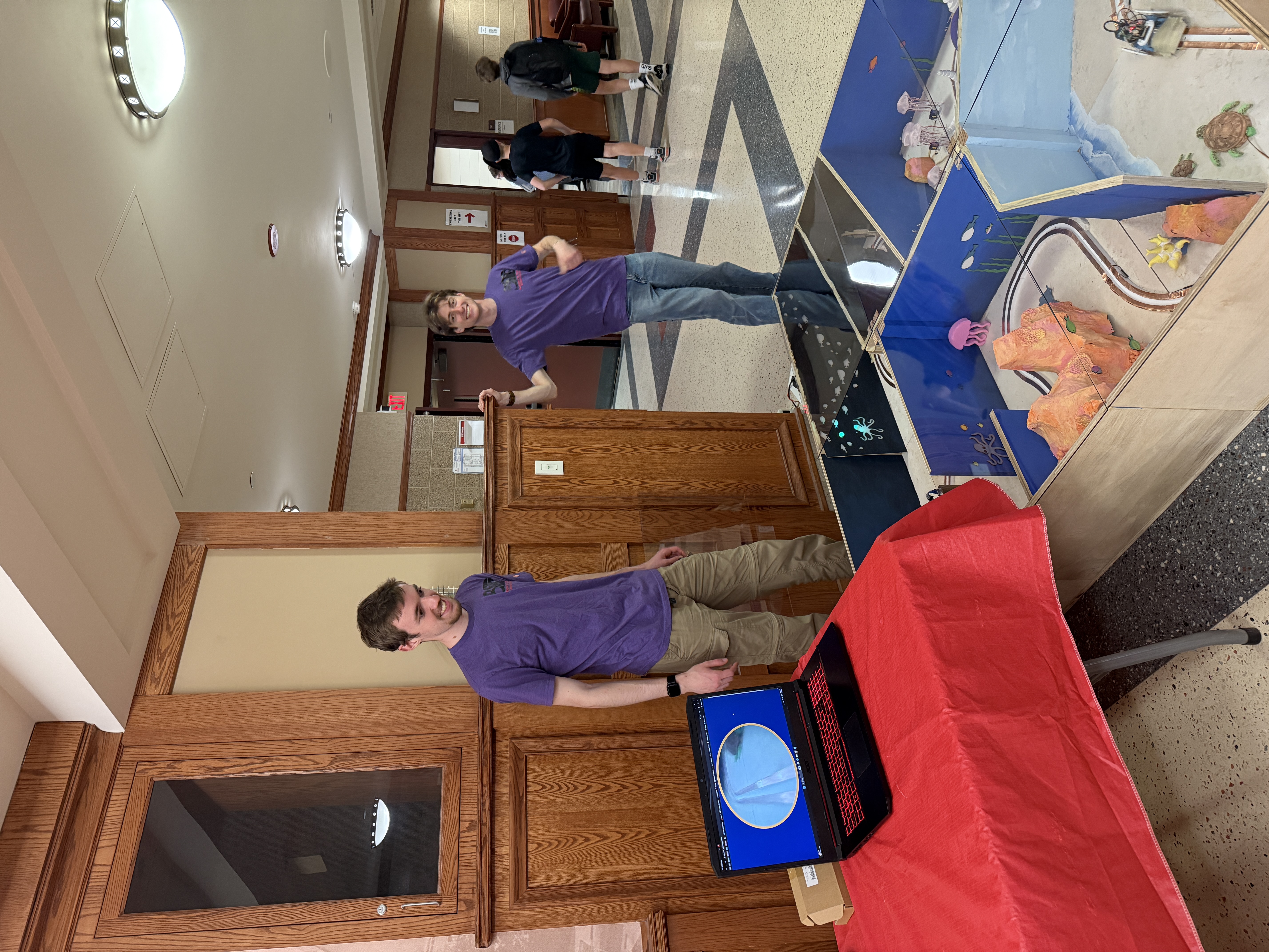
The model was demonstrated at Engineering Expo as part of the booth that won Best in Show. This year it is being upgraded from the single continuously moving vehicle to a three-vehicle system with block zones and timed dispatches, along with additional animatronics, moving the model closer to how a real dark ride manages throughput and spacing.

Gallery
Show-scene brainstorm on the whiteboard
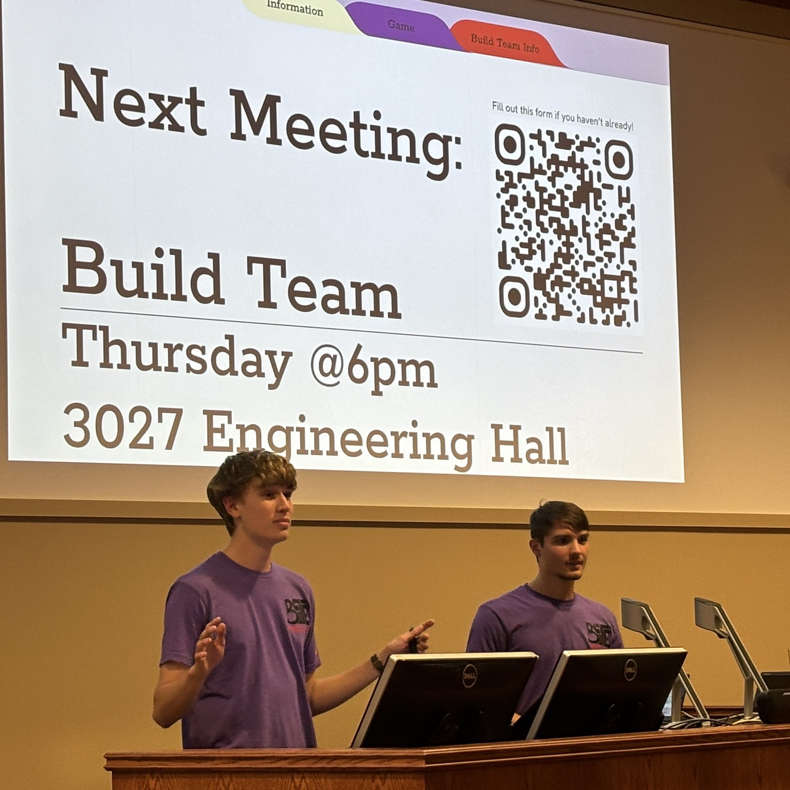
Build-team recruiting presentation
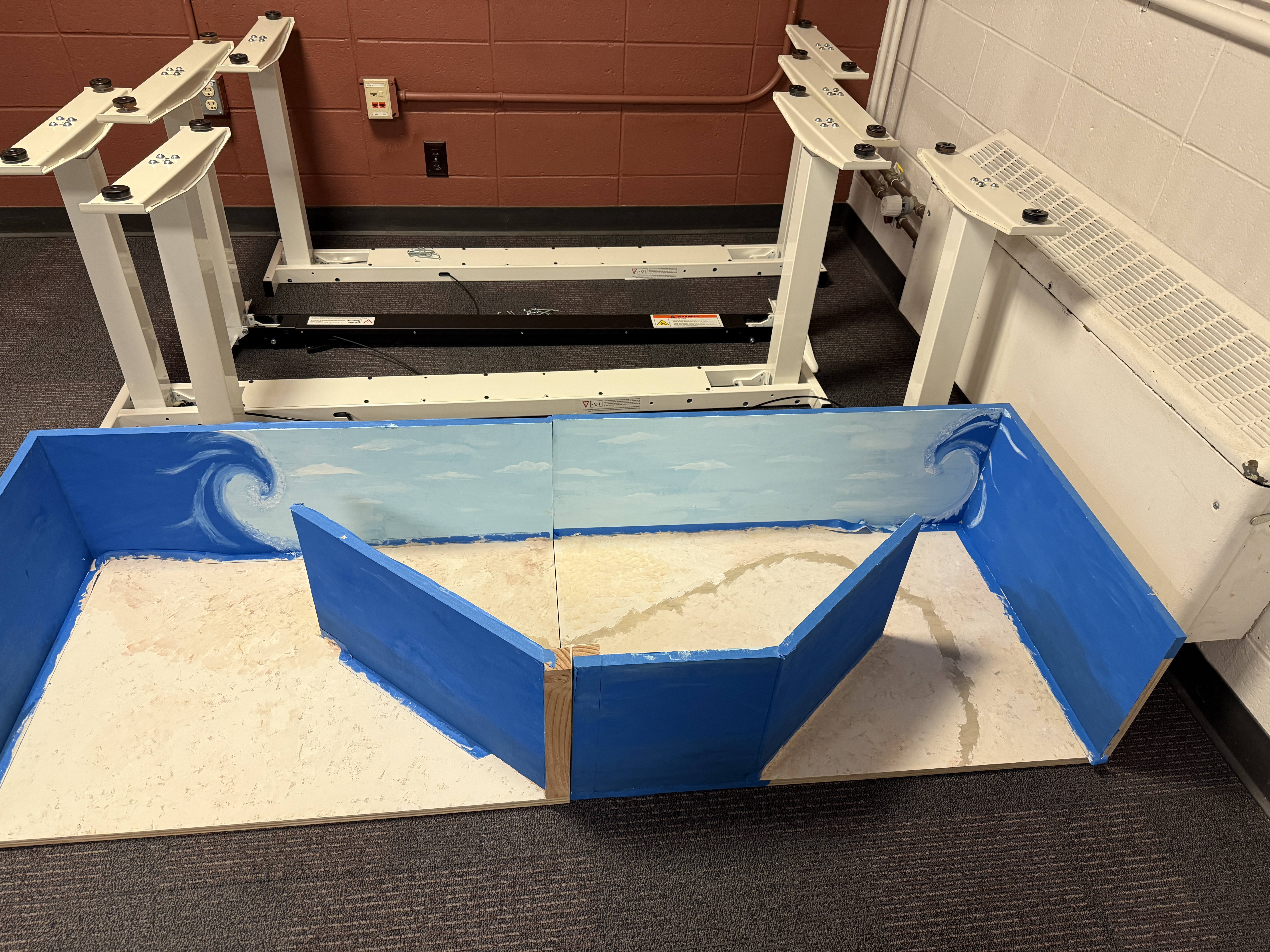
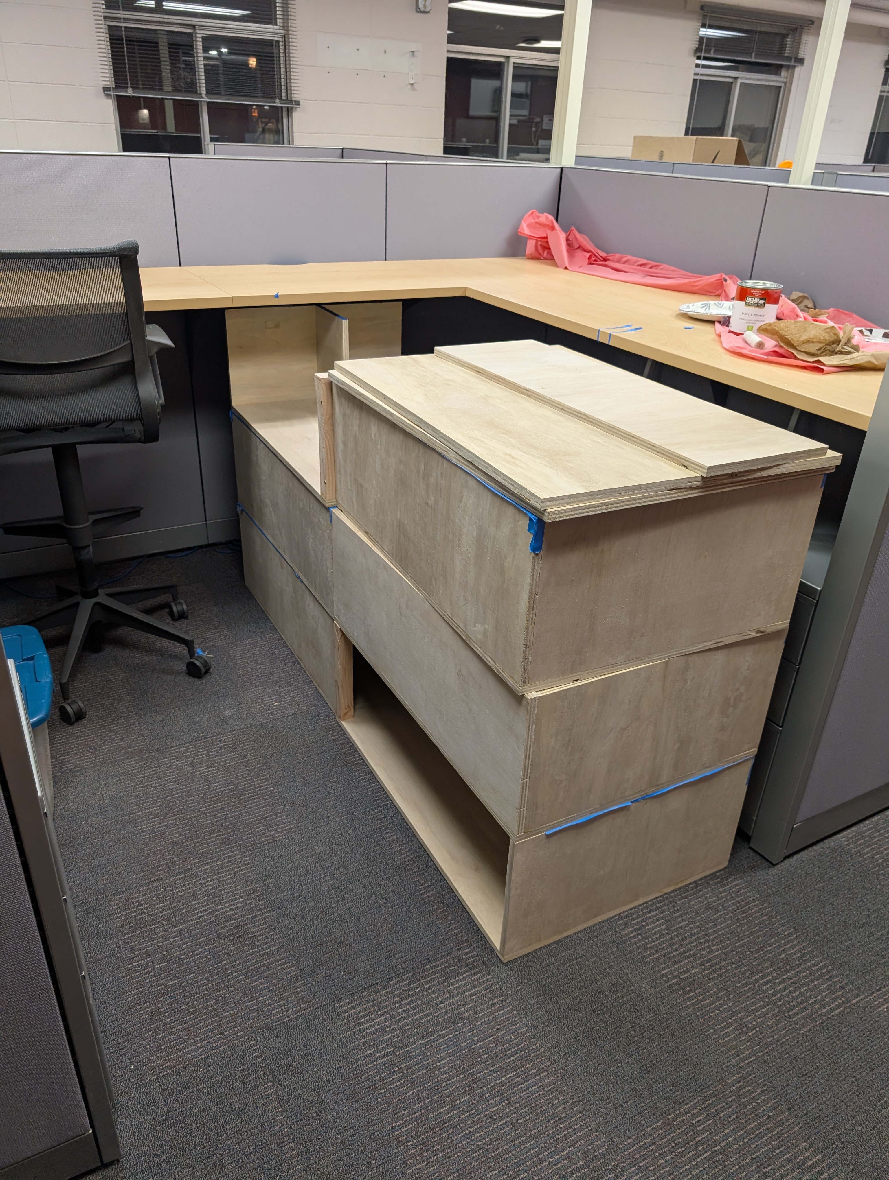
Ride enclosure under construction
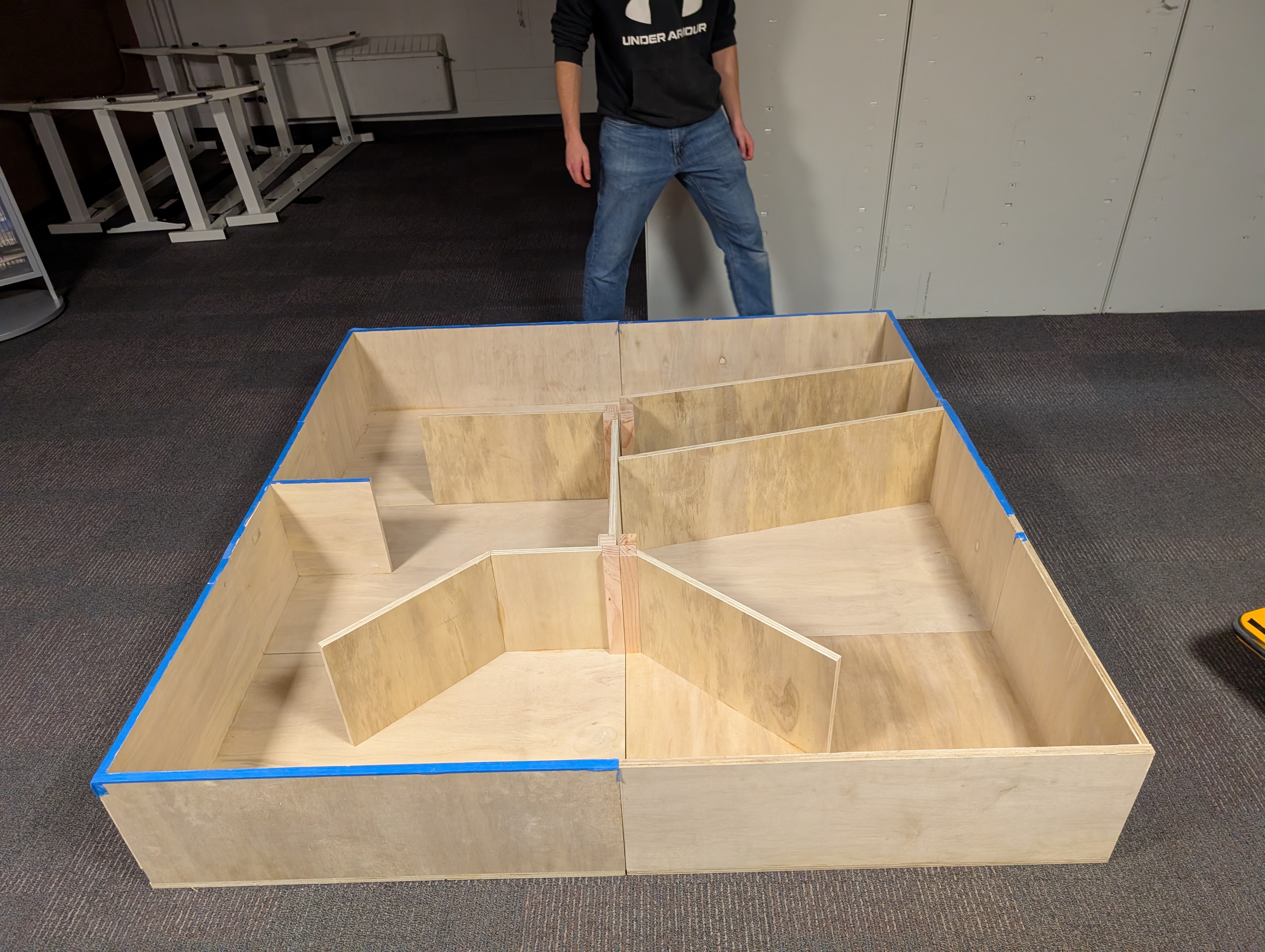
Show-scene dividers assembled in the enclosure
Painted ocean scenery for the show set
Finished ride with track and animatronics
The dark ride demonstrated at Engineering Expo
Additively manufactured aircraft engine fuel nozzle
Role
Author
Type
Trade Study
Tools & Technologies
Technical Writing Weighted Trade Study Aerospace Manufacturing
06  —  Report

Additive vs. Subtractive Manufacturing for Aircraft Engine Components

A weighted trade study of two routes for jet-engine parts

A technical report evaluating whether additive or subtractive manufacturing is the better fit for producing aircraft engine components, written to persuade a mixed audience of engineers and non-technical stakeholders.

↓Scroll for the full write-up
Method & Result

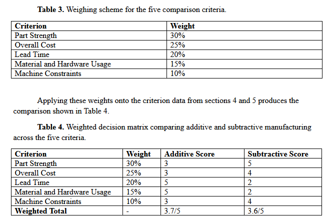
I built the comparison around a weighted scoring of the criteria that actually drive a production decision: material efficiency, lead time, part strength, proven failure history, and scale economics. When the numbers came back, the two methods landed in a near tie. That result was more useful than a clean winner would have been, because it meant the real answer was not "which method is better" but "which method is better for which component." I owned the comparative analysis, the recommendation, and the conclusions and next-steps sections of the report.

Recommendation

My recommendation was scoped rather than universal. Additive manufacturing makes sense for components with complex internal geometries and lower production volumes, like fuel nozzles or parts with internal cooling routes that subtractive methods physically cannot produce. Those are exactly the cases where additive's lead-time and material-efficiency gains matter most, and where its weaker part-strength score and risk of layer separation matter least, since the parts run in small batches and can be inspected individually. Subtractive manufacturing should stay the standard for high-volume, high-risk parts like housings and brackets, where proven strength records and scale efficiency outweigh any material savings.

Mitigations

The recommendation only holds up if the risks are handled directly, so I paired it with three mitigations. Certification should roll out in phases, starting with non-critical components, so failure data can accumulate under low-stakes conditions before additive parts are trusted anywhere flight-critical. Z-pinning and finish machining should become standard practice for additive components, since both measurably close the fatigue gap between additive and wrought material. Adoption should come with workforce retraining, enabling machinists with deep subtractive experience get redirected onto additive lines rather than displaced. I also worked through the ethical dimension of that last point, since a manufacturing shift like this has real consequences for the people running the floor.

In Summary

The report demonstrates technical writing for a split audience, analytical rigor in reaching a defensible recommendation from an ambiguous result, and working domain knowledge of aerospace manufacturing.

Gallery
Weighted decision matrix comparing additive and subtractive manufacturing across five criteria
Report title slide: Optimization of Aircraft Engine Production — A Comparison of Competing Manufacturing Techniques
Attend. product screenshot
Role
Founder
Status
In pilot
Domain
Graph Theory
Tools & Technologies
Python Graph Theory FastAPI PostgreSQL Azure Microsoft Graph API Microsoft Entra
05  —  Project

Attend.

Mass meeting scheduler on custom graph algorithms

A B2B Outlook add-in that plugs into Microsoft 365 and schedules mass meetings automatically, on a graph-theory optimizer I designed.

Attend is a startup I founded, funded, designed, and built myself. It came out of a year of professional engineering management work, where I watched a huge amount of time disappear into meetings: meetings that ran too long for what they accomplished, meetings too short to matter, meetings with the wrong people in the room, and, worst of all, the endless back-and-forth of just getting them scheduled. Coordinating a large meeting today means manually juggling everyone's availability, priority, and room constraints by hand, and no existing product actually solves that. They schedule what you tell them to. None of them find the optimal time and routing on their own.

↓Scroll for write-up
How it works

So I built the thing that should exist. Attend is a B2B Outlook add-in that plugs into Microsoft 365 and schedules mass meetings automatically. At its core is a graph-theory-based optimizer I designed: it first guarantees every required attendee can actually make it, then maximizes how many optional attendees can join, then optimizes room selection by capacity and travel distance. It pulls live availability through the Microsoft Graph API, intersects everyone's free time, and returns the genuinely best slot rather than the first one that technically works.

Built solo

The part I am most proud of is that I built all of it solo, and most of it was territory I had never touched. Going in, I knew basic Python and nothing else. To ship this I taught myself graph theory to build the optimizer, and the entire Azure hosting and backend world to run it: an async FastAPI backend, a multi-tenant PostgreSQL database with proper tenant isolation, secure Microsoft Entra authentication, and cloud hosting and storage. I funded the whole thing out of my own student accounts.

The record

Attend is in pilot use now. More than the product itself, it is the clearest evidence of how I work: I find a real problem, I decide it is worth solving, and I go learn whatever I have to in order to solve it well.

5-DOF robotic arm attraction model
Role
Solo — design, analysis, build
Year
2026
Status
In fabrication
Tools & Technologies
SolidWorks Cycloidal drive FEA Inverse kinematics ESP32 TMC2209
01  —  Project

5 DOF Robotic Arm Attraction Model

Fully Custom Arm Down to the Actuator

A solo-designed, desktop-scale working model of a “KUKA coaster” — the robotic-arm attraction type where a passenger capsule rides the end of a multi-axis industrial arm through a programmed motion profile. The scale patron is a 6″ Bucky Badger figure seated in a fully ASTM F2291 Class-4 compliant restraint, and the platform is modular, so one arm can run different ride profiles rather than being locked to a single motion.

↓Scroll for write-up & gallery
The drivetrain

The arm has five joints, giving it five degrees of freedom — one rotational axis per joint. Every joint is driven through a cycloidal reduction I designed from scratch: a 20:1 stage with 21 fixed ring pins acting against a 20-lobe disc, run as a dual-disc pair set 180° apart so the eccentric masses balance each other. I generated the disc profile mathematically and imported it into SolidWorks equation driven curves, then packaged it around a 2.43″ pitch circle with 0.04″ of eccentricity. I chose cycloidal over harmonic drives for the two reasons that matter on a ride: near-zero backlash for repeatable motion, and tolerance for the shock loads a start-stop ride profile throws at the joints.

Actuation & control

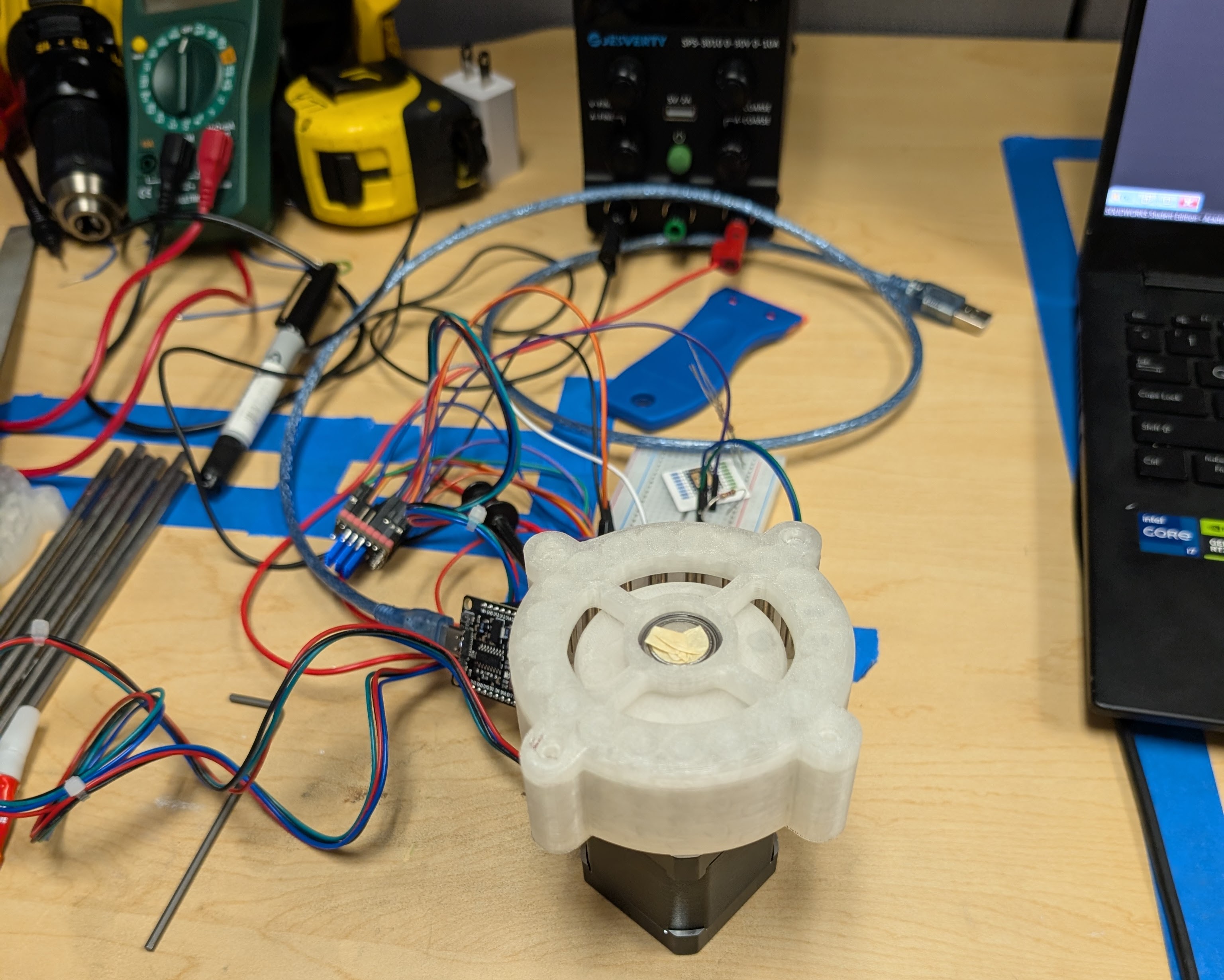
Actuation is a NEMA 17 stepper per joint driven by TMC2209 drivers, with motor current set in software over UART rather than by trimpot, all coordinated by an ESP32. A GT2 timing-belt stage sits between each motor and its cycloidal input, which offsets the motor axis for tighter packaging and leaves room to add reduction if a profile needs it.

The restraint

Because the ride profile I targeted put the model in Class-4 territory, the restraint had to meet that bar in full. I designed a dual-redundant, ratcheting over-the-shoulder lap bar that is compliant both mechanically and electrically, so a single failure in either domain does not release the patron.

The analysis

The design is backed by real analysis, not just CAD: torque and load calculations at the joints, inverse kinematics for the arm, FEA on the loaded members, and a full dynamic-systems analysis of the ride arm through its motion.

The record

Full CAD assembly is complete, the cycloidal drive is built, and the arm segments are in fabrication now.

Gallery
3D-printed cycloidal drive, ring pins and dual-disc pair
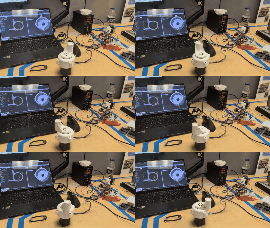
Ride arm running a motion profile on the bench
Cycloidal joint driven by a NEMA 17 stepper on the test bench
Folding projector robot — Beam Buddy CAD render
Role
Design & Team Lead
Team
4 members
Type
Design Study
Tools & Technologies
SolidWorks Geometric Modeling Mechanism Design Technical Drawing GD&T
08  —  Study

Folding Projector Robot

Concept design study — geometric modeling final

A design project from my geometric modeling final, where the brief was to design a fictional piece of technology and take it from concept through full CAD. I designed a WALL-E-style projector robot built around one idea: it collapses down to the size of a water bottle for easy carrying, then unfolds — legs and a head deploy out of the packed body — to stand itself up and frame a projected image squarely against a wall.

↓Scroll for write-up & gallery
The mechanism

The concept is backed by a real mechanism, not just a nice shape. The folding and deployment are worked out underneath the design, so the legs and head actually have a path from stowed to standing rather than magically rearranging. I ran a center-of-gravity check to confirm the deployed robot stands stably on its own legs, which is the constraint that makes or breaks a fold-out form like this.

Concept to CAD

I owned the design from paper to model: concept sketches, geometric dimensioning, orthographic drawings, and the mechanism layout, then led a 4-person team to take it into CAD. Leading the CAD effort meant setting the assembly structure, dividing the components across the team, and keeping everyone's parts consistent so the pieces actually fit together in the final assembly.

What it shows

The project stayed a design study rather than a build, but it demonstrates concept-to-CAD design leadership: generating an original mechanism on paper and driving a team to realize it as a coherent, buildable model.

Gallery
Folding projector robot — design document, page 1
Folding projector robot — design document, page 2
Folding projector robot — design document, page 3
Folding projector robot — design document, page 4
Beam Buddy exploded view with parts list
Beam Buddy rendered in use
The Record
Where the work happened

Track Record

Professional Experience
Walt Disney Imagineering
Jan ✦ Jun 2026
Glendale, California
Project Engineer Intern

Walt Disney Imagineering

By L. Rudolph · Ride, Show & AD&E studios

Glendale, Calif. — Coordinated cross-discipline design across 3 concurrent projects in 2 portfolios — managing model & sheet release, issue-resolution tracking, and clash detection in Autodesk Forma to hold drawing-control integrity across studios.

  • —Led weekly work sessions of 95+ stakeholders across Ride, Show, and AD&E studios to resolve design issues and align scope, schedule, and budget milestones.
  • —Conceived and championed a novel lift system for critical show-element maintenance access, advancing it through design-review cycles to full project adoption.
  • —Ran spatial, solar, and interference studies in Revit, Navisworks, and SolidWorks, and built 4+ Airtable databases (issue log, scheduler, integration framework) to centralize cross-studio tracking.

J.H. Findorff & Son
May ✦ Dec 2025
Madison, Wisconsin
Project Engineer Co-Op

J.H. Findorff & Son

By L. Rudolph · $286M student-housing high-rises

Madison, Wis. — Managed two Madison student-housing high-rises totaling $286M, coordinating design and construction while ensuring compliance with plans, drawings, and municipal code.

  • —Engineered a high-capacity loading dock for 5 concurrent deliveries of varying truck sizes — eliminating road closures while keeping forklift and waste operations flowing.
  • —Designed an in-wall blocking system for all mounted fixtures with FEA validation and ADA-compliant variants meeting accessibility requirements.
  • —Designed and validated a custom post-tension survey tool in SolidWorks, cutting engineer survey time 4×; authored $264K in interior, amenity, road, and safety contracts.
Leadership Experience
BiTE
2024 ✦ Now
Madison, Wisconsin
Co-Founder & Operations Officer

Badgers in Themed Entertainment

By L. Rudolph · Chief Engineer & Project Director

Madison, Wis. — Founded and lead B.i.T.E., a registered engineering student organization now 340+ members strong.

  • —Direct CAD design and fabrication expo projects, setting scope, schedule, and build standards across teams.
  • —Organize teams for TMU Thrill Design competitions and ASTM F24 Task Group meetings.
  • —As Chief Engineer and Project Director, engineered mechanical assemblies of 580+ components in SolidWorks — ensuring kinematic function and manufacturing tolerances across the build.
Visit bite.engr.wisc.edu →
In the News
Coverage of the work

Press Clippings

UW Engineering
Mar 2026

In the loop: New student organization is taking Badgers for a ride

UW–Madison College of Engineering profiles the founding of BiTE and its mission to bring engineers into themed entertainment.

→
Wisconsin Engineer
Aug 2026

Take a bite out of starting a new club

The student-run magazine, in print since 1896, tells how two mechanical engineers turned a lecture-hall icebreaker into Badgers in Themed Entertainment.

→
Honours
On the record

Recognition

2026

IAAPA Foundation Experiential Scholarship

Awarded by the IAAPA Foundation to support study toward a career in the attractions industry.

2023-2026

Dean's List, College of Engineering

Named to the Dean's List all six semesters at Wisconsin–Madison.

2024

Robert J Mensel Merit Scholarship

Awarded by the College of Engineering for academic standing.

The Particulars
Tools of the trade

Toolkit

CAD / Modeling
SolidWorks
Autodesk Inventor
Revit
Navisworks
Analysis
FEA
Kinematic Analysis
EES
Python
Safety & Standards
ASTM F24
ASTM F2291 Class-4
Restraint Systems
Human Factors
Fabrication
3D Printing
CNC Milling
Laser Cutting
Wood Fabrication
BIM / Coordination
Autodesk Forma / ACC
Autodesk Build
Clash Detection
Bluebeam
Project Controls
Scheduling · MS Project
Airtable
Scope & Budget
Document Control
Documents · For the record

Download Résumé

PDF · Updated 2026 · One page
↓
Correspondence
Letters to the editor, welcome.
levilrudolph@gmail.com
LinkedIn → Résumé →
⁂
The Rudolph Record

Set in Fraunces and Newsreader. Printed on newsprint, in Madison, Wisconsin.

© 2026 Levi RudolphDesigned & EngineeredAvailable for 2026